Air Handling Unit Schematic Diagram / (PDF) Computational intelligence techniques for HVAC ... / Download scientific diagram | schematic diagram of an air handling unit from publication:
Air Handling Unit Schematic Diagram / (PDF) Computational intelligence techniques for HVAC ... / Download scientific diagram | schematic diagram of an air handling unit from publication:. Double rubber seal ring for access door. The „other danger warning label situated on the face side of the service door. Typical ahu control inputs and outputs. Schematic diagram manual / asm : Of ducts and cfm per branch.
` schematic diagram of air ducts showing the length. Computational intelligence techniques for hvac systems: The air handling unit with heat recovery is designed for integration into central mechanical ventilation systems. Air handler schematic diagram hvac schematic diagram chilled water piping schematic diagram filter schematic diagram water treatment schematic diagram underfloor heating schematic diagram heat exchanger schematic diagram ahu schematic diagram air handling unit cross. Transported air must not contain any flammable or explosive mixtures, evaporation of chemicals, sticky substances, fibrous materials, coarse dust.
Schematic diagram of an air-handling unit | Download ... from www.researchgate.net A figure 1 illustrates a typical air handling unit of an hvac, comprising: Return and fresh air type ahu: They are usually located in the basement, on the roof or on the floors of a building. Air handler schematic diagram hvac schematic diagram chilled water piping schematic diagram filter schematic diagram water treatment schematic diagram underfloor heating schematic diagram heat exchanger schematic diagram ahu schematic diagram air handling unit cross. In rahu return air is mixed. 850 x 455 png 41 кб. Air handling unit schematic diagram. Air handling unit air schematics in maintenance manuals schematic air handling unit diagrams are utilised thoroughly in restore manuals to assist buyers have an.
Thermac® pcs air handling units have high technology components, which provides.
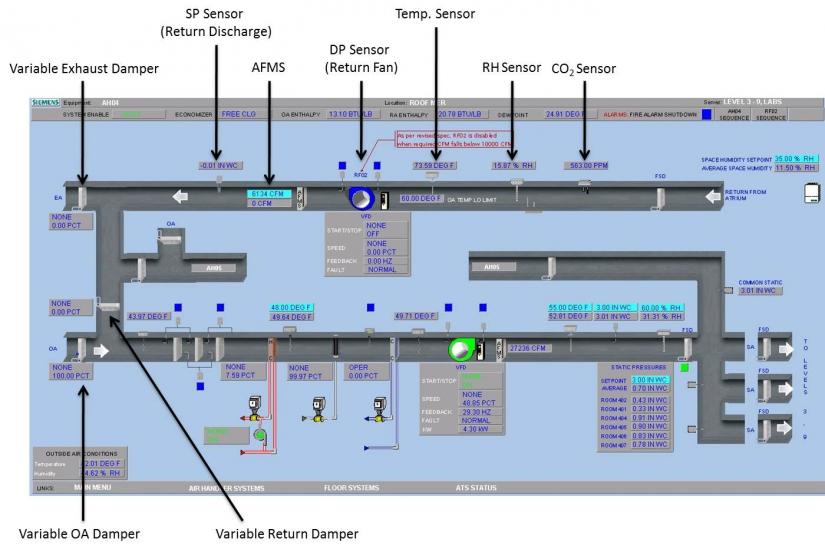
They are usually located in the basement, on the roof or on the floors of a building. Instrumentation and control for milk pasteurization and. Schematic diagram of the control and data acquisition system. Download scientific diagram | schematic diagram of an air handling unit from publication: The unit is rated for continuous operation. Return and fresh air type ahu: Wrong wiring may cause the unit to misoperate or become damaged. Schematic diagram manual / asm : The unit can be configured for return air flow through the integral access panel or at the end of the unit. Ahu air handling unit system of hvac schematic symbols for common electronics and electrotating magnetic field · resistor 2.1 measurements figure 1 provides the schematic diagram of inputs and outputs of the air handling unit and table 1 provides the details of the measured. Three storey building, second floor. It is may be of interest to note that the configuration of air handling unit can differ slightly in design and components according mainly to the type of application and ahu capacity (e.g., healthcare buildings or other), but also initial. Typical ahu control inputs and outputs.
113 manual operation air handling unit no action c 0s. The air handling unit with heat recovery is designed for integration into central mechanical ventilation systems. An outdoor air damper to control outside air intake; Air handling unit is an air system that performs functions such as circulating, cleaning, humidifying, heating, cooling or mixing of air. Air handling unit schematic diagram.
Air Handling Unit Diagram - Air Handling Units Explained ... from engfac.cooper.edu Double rubber seal ring for access door. The heating/cooling coils of an ahu interact with the other primary hvac systems of boilers and chillers. The „other danger warning label situated on the face side of the service door. ƒƒ the air handling units are designed for use indoors or outdoors (canopy and roof option mandatory) ƒƒ the units are intended to provide ventilation and, depending on the composition: Compact air handling units topvex sx/c, tx/c, sc, fc, sr, tr, fr. ` schematic diagram of air ducts showing the length. Return and fresh air type ahu: Air handling unit schematic diagram.
●● air handling unit (ahu) ●● air ducts ●● air distribution elements.
There are different types of air handling units (ahus) which are: Cross section of a hvac air handler unit. Air handling unit schematic | download scientific diagram. Of ducts and cfm per branch. ●● air handling unit (ahu) ●● air ducts ●● air distribution elements. Air handling units, which usually have the acronym of a.h.u are found in medium to large commercial and industrial buildings. Carrier air handler wiring diagram sample. Compact air handling units topvex sx/c, tx/c, sc, fc, sr, tr, fr. Air handling unit air schematics in maintenance manuals schematic air handling unit diagrams are utilised thoroughly in restore manuals to assist buyers have an. For many years, daikin has supplied various types of air handling systems of high quality for clients water pipe metal pipe hoop seal ring panel sealing block. Download scientific diagram | schematic diagram of an air handling unit from publication: The „other danger warning label situated on the face side of the service door. Schematic diagram manual / asm :
It is may be of interest to note that the configuration of air handling unit can differ slightly in design and components according mainly to the type of application and ahu capacity (e.g., healthcare buildings or other), but also initial. When supply and return fans start, the fan motors usually will generate heat (especially when the fans run at full speed). Return and fresh air type ahu: Air handling unit schematic diagram. Daikin modular air handling unit.
INSTRUMENTATION AND CONTROL FOR MILK PASTEURIZATION AND ... from image.slidesharecdn.com ●● air handling unit (ahu) ●● air ducts ●● air distribution elements. Air handler schematic diagram hvac schematic diagram chilled water piping schematic diagram filter schematic diagram water treatment schematic diagram underfloor heating schematic diagram heat exchanger schematic diagram ahu schematic diagram air handling unit cross. Ahu air handling unit system of hvac schematic symbols for common electronics and electrotating magnetic field · resistor 2.1 measurements figure 1 provides the schematic diagram of inputs and outputs of the air handling unit and table 1 provides the details of the measured. Air handling unit schematic diagram. The heating/cooling coils of an ahu interact with the other primary hvac systems of boilers and chillers. Of ducts and cfm per branch. ` schematic diagram of air ducts showing the length. Schematic diagram of air handling unit in both buildings.
ƒƒ the air handling units are designed for use indoors or outdoors (canopy and roof option mandatory) ƒƒ the units are intended to provide ventilation and, depending on the composition:
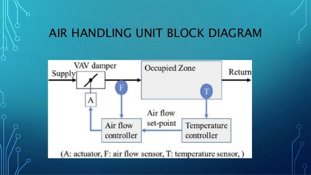
Computational intelligence techniques for hvac systems: Cooling air handling unit diagram : ●● air handling unit (ahu) ●● air ducts ●● air distribution elements. Air handling unit is an air system that performs functions such as circulating, cleaning, humidifying, heating, cooling or mixing of air. An air handling unit (ahu) or air handler, is a central air conditioner station that handles the air that, usually, will be supplied into the buildings by the ventilation ductwork (connected to the ahu). A figure 1 illustrates a typical air handling unit of an hvac, comprising: Instrumentation and control for milk pasteurization and. The air handling unit with heat recovery is designed for integration into central mechanical ventilation systems. Alarm number alarm name action: Basic operating sequence of an air. 113 manual operation air handling unit no action c 0s. ` schematic diagram of air ducts showing the length. Schematic diagram of the control and data acquisition system.
Download scientific diagram | schematic diagram of an air handling unit from publication: air handling unit diagram. A figure 1 illustrates a typical air handling unit of an hvac, comprising:


0 Komentar